Nortec On Digital Duct Humidistat User Manual
Browse online or download User Manual for Equipment Nortec On Digital Duct Humidistat. Nortec On Digital Duct Humidistat User Manual
- Page / 4
- Table of contents
- BOOKMARKS
Rated. / 5. Based on customer reviews
2549737-D | 22 July 2014 Introduction | 1
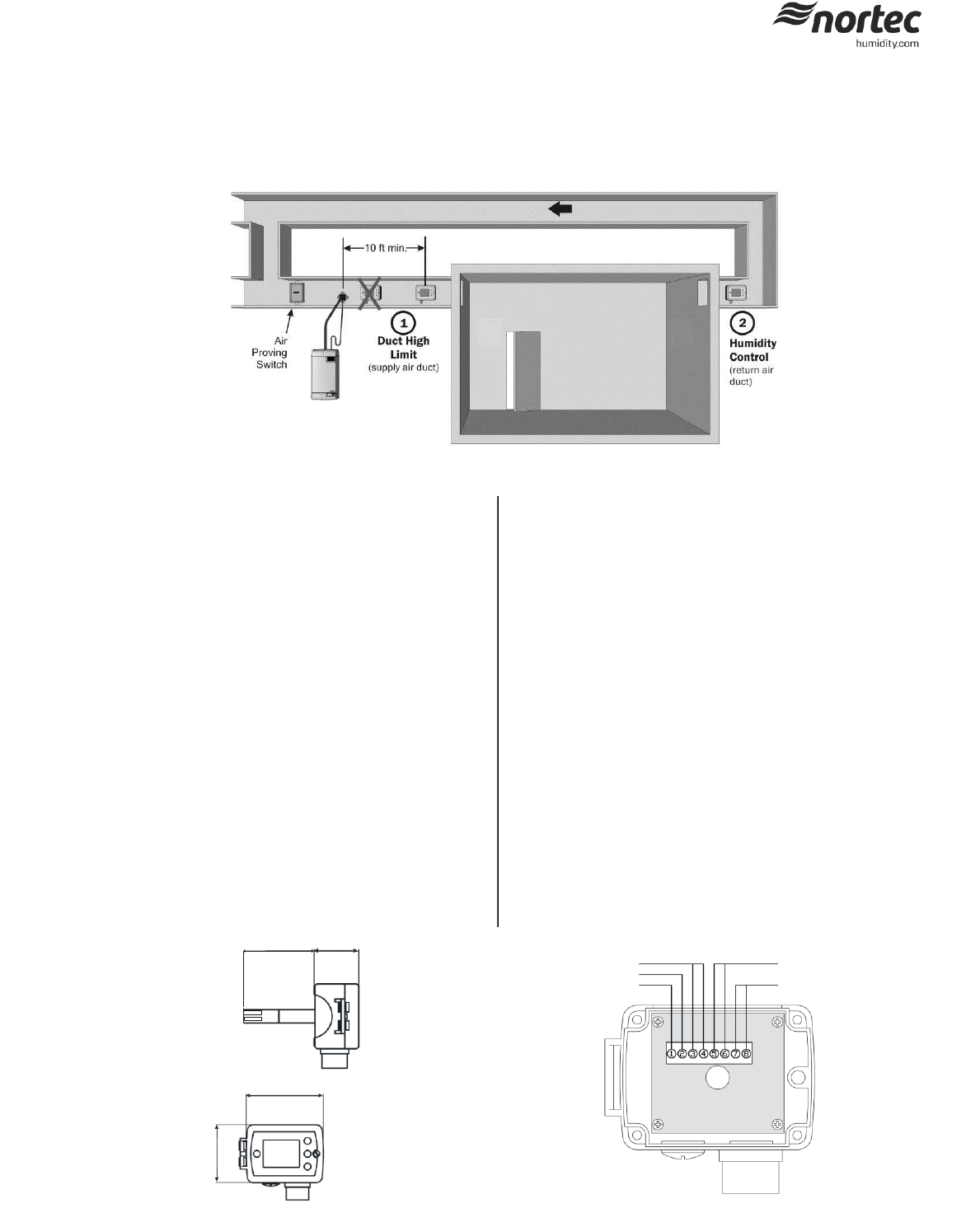
1 - Duct High Limit Installation
When installed as a high limit, the humidistat prevents over humidification as
well as wetting of the supply duct. Do not use fan relay when configuring as a
high limit.
Location:
1 Install directly on the supply duct in an area where the air is well mixed with
uniform flow.
2 Install downstream of the steam distributor at a distance 1.5 times the
absorption distance (typically 10-12 feet or 3-3.7 m). Must be in a location to
sense high humidity in addition to sensing when representative air is over
humidified or approaching saturation.
Installation:
1 Use the provided humidistat template and small level to mark outline of
humidistat body and location of probe hole. Ensure template is level before
marking.
2 Open the housing by removing the screw securing the face of the housing.
3 Drill a 5/8” (16 mm) hole in the duct at the marked location for probe
insertion.
4 Insert the probe into the air stream and place humidistat against duct wall.
5 Secure the duct humidistat to the duct using 4 sheet-metal screws (#6 x 3/4”
Phillips).
6 Wire as per wiring diagram 2548733 in this document.
7 Close the cover and secure using the screw removed in step 2.
Configuration:
1 Using keypad, set humidity to specified level (85% maximum) as a safety to
prevent saturation.
On/Off Digital Duct Humidistat Installation Instructions
This document covers the operation and installation instructions for the following digital humidistat:
Part #: 2548732
Description: On/Off Duct Humidistat
The humidistat can be configured for either humidity control or as a high limit safety device:
76 (3.0)
47 (1.9)
91 (3.6)
68 (2.7)
Humidify Relay
24 Vac
Com
Fan (Furnace)Relay
NTC Sensor
Figure 2: Dimensions
Figure 3: Terminal Strip
Figure 1: Duct Humidistat Installation Locations
2 - Humidity Control Installation
When configured as a humidity controller, the humidistat provides
accurate control of the RH in a return duct and will activate/deactivate
a furnace or circulation fan.
Location:
1 Install on the return air duct, close to the air inlet but upstream from
a return fan if one is present.
Installation:
1 Use the provided humidistat template and small level to mark outline
of humidistat body and location of probe hole. Ensure template is
level before marking.
2 Open the housing by removing the screw securing the face of the
housing.
3 Drill a 5/8” (16 mm) hole in the duct at the marked location for
probe insertion.
4 Insert the probe into the air stream and place humidistat against
duct wall.
5 Secure the duct humidistat to the duct using 4 sheet-metal screws
(#6 x 3/4” Phillips).
6 Wire as per wiring diagram 2548733 in this document. Figure 3
outlines the terminal layout.
7 Close the cover and secure using the screw removed in step 2.
Configuration:
1 Using keypad, set specified humidity level. For general health and
comfort, a humidity setting of 50% is recommended.
2 See Table 3 for outdoor temperature setback configuration, if
optional outdoor temperature sensor is supplied (P/N 2520263 or
2553858).
- Humidify Relay 1
- Fan (Furnace)Relay 1
- NTC Sensor 1
- Power Failure 3
- 4 4
Summary of Contents
Page 1 - NTC Sensor
2549737-D | 22 July 2014 Introduction | 1 1 - Duct High Limit Installation When installed as a high limit, t
Page 2
2 | Introduction Duct Humidistat LCD Display 45.5%35.0%1234675 Legend: 1 Display of current humidity value. 2 Display of setpoint 3 Snowflake
Page 3 - Power Failure
2549737-D | 22 July 2014 Introduction | 3 Table 4: Technical Specification Power Supply Operating Voltage 24 V
Page 4 - 4
4 | Introduction
Related products and manuals for Equipment Nortec On Digital Duct Humidistat
Equipment Nortec SETC Outdoor User Manual
 (32 pages)
(32 pages)
Equipment Nortec SE Series User Manual
(100 pages)
(100 pages)
Equipment Nortec MES2 User Manual
(54 pages)
(54 pages)
Equipment Nortec LINKS XPS MH User Manual
(68 pages)
(68 pages)
Equipment Nortec LINKS 2 SETC B+ User Manual
(23 pages)
(23 pages)
Equipment Nortec Modbus User Manual
(52 pages)
(52 pages)
Equipment Nortec RH2+ User Manual
(62 pages)
(62 pages)
Equipment Nortec Blower Packs User Manual
(31 pages)
(31 pages)
Equipment Nortec BACnet User Manual
(36 pages)
(36 pages)
Equipment Nortec NH-EL Series User Manual
(99 pages)
(99 pages)
Equipment Nortec ME Direct Feed User Manual
(40 pages)
(40 pages)
Equipment Nortec ME Control User Manual
(76 pages)
(76 pages)
© 2020, manymanuals.com. All rights reserved. | 0.427 s |
 Manymanuals.com
 Manymanuals.de
 Manymanuals.fr
 Manymanuals.it
 Manymanuals.pl
 Manymanuals.cz
 Manymanuals.es
 Manymanuals-pt.com
Comments to this Manuals